How to use wire strippers safely?

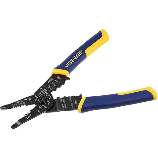
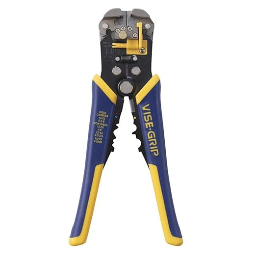
Wire strippers are a fundamental tool in the toolkit of every electrician and handyman, and knowing how to use them safely is crucial. Our blog post, ‘How to Use Wire Strippers Safely,’ provides a detailed, step-by-step guide on their proper and safe usage. These tools are indispensable in electrican work, designed to remove insulation from wires without harming the conductive core. Our guide aims not only to enable users to effectively employ wire strippers but also to prevent accidents and injuries commonly associated with incorrect usage.
Table of Contents
We’ll cover essential topics such as selecting the right wire stripper for your task, understanding different types of wire strippers, and the proper techniques for stripping wire. Additionally, we’ll delve into safety tips to avoid electrical shock and other hazards, and discuss maintenance practices to keep your wire strippers in top condition. By the end of this guide, users will have gained comprehensive knowledge and skills to handle wire strippers safely and efficiently in any electrical project.
Top-Rated Wire Strippers for Professionals


A Comprehensive Guide on How to Properly Utilize Wire Strippers
1. Step 1: Wear appropriate safety gear
- Put on safety goggles. Place the safety goggles securely over your eyes to protect against any flying debris or sparks. For example: Place the goggles over your eyes ensuring a snug fit, with the lens covering both eyes completely.
- Wear gloves. Put on gloves to safeguard your hands from potential cuts or burns. Choose gloves that are specifically designed for the task at hand, such as heat-resistant or cut-resistant gloves. For example: Put on a pair of heat-resistant gloves before handling the wire strippers to protect your hands from burns.
- Use other necessary protective equipment. Identify any additional protective gear required for the specific task and wear it accordingly. This could include items such as safety shoes, earplugs, or protective clothing. For example: If working with loud machinery, insert earplugs to protect your hearing.
Remember, wearing appropriate safety gear is essential before using wire strippers or engaging in any potentially hazardous activity. Guide: Electrician Similar Occupations


2. Step 2: Inspect the wire stripper
To check the condition of the wire stripper, follow these steps:
- Inspect the blades: Ensure that the blades are sharp and in proper alignment. Look for any signs of wear, such as nicks or dents. A damaged blade might not strip the wire properly, leading to a poor connection.
- Examine the handles: Check the handles for any cracks or loose parts. A damaged handle could compromise the user’s grip and result in an unsafe operation. Verify that the handles have a non-slip surface for better control.
- Assess the adjustment mechanism: Test the adjustment screws or dials to make sure they move smoothly and lock securely in place. If the mechanism is loose or stiff, it may impact the stripping precision or cause the wire stripper to slip during use.
- Verify the insulation cutter: Confirm that the wire stripper has a built-in insulation cutter and that it is in good condition. The cutter should cleanly and effortlessly remove the insulation from the wire without damaging the conductor. Top 7 Wire Crimpers for Effective Results in 2024
Remember, a thorough inspection of the wire stripper is crucial to ensure its effectiveness and safety.
3. Step 3: Select the appropriate wire gauge
To select the appropriate wire gauge on the wire stripper, follow these steps:
- Identify the size of the wire you are working with. This information can usually be found on the insulation of the wire or in the wire’s specifications.
- Match the wire size with the corresponding gauge setting on the wire stripper. Most wire strippers have multiple gauge options to accommodate different wire sizes.
- For example, if you are working with a 10-gauge wire, set the wire stripper to the 10-gauge setting.
- If the wire size is not labeled in gauge, you can use a wire gauge tool or a conversion chart to determine the gauge of the wire.
- Ensure that the wire is securely held by the wire stripper before applying pressure to strip the insulation. Make sure to use the correct gauge setting to avoid damaging or cutting the wire.
Following these steps will ensure that you choose the correct wire gauge setting on the wire stripper and perform the stripping process accurately and safely.


4. Step 4: Position the wire in the stripper
To position the wire in the stripper, follow these steps:
- Hold the wire stripper firmly in one hand.
- Place the wire between the jaws of the wire stripper, ensuring that the insulation is facing towards the cutting portion of the tool.
- Adjust the wire stripper if needed, making sure the cutting edges align with the insulation.
- Close the jaws of the stripper gently until they grip the wire securely but without damaging it.
- Double-check the position of the wire to ensure it is correctly aligned for stripping.
For example, when stripping a 14-gauge wire, position it within the stripper so that the cutting edges are aligned with the insulation while avoiding any contact with the wire strands.
By following these instructions, you will correctly position the wire in the stripper, allowing for precise and efficient stripping.
5. Step 5: Squeeze the handles
To properly execute Step 5, gently grip the handles of the wire stripper ensuring a secure hold. Apply controlled pressure by squeezing the handles together, allowing the jaws of the wire stripper to cut through the insulation of the wire. This will create a precise and clean cut, enabling easy access to the conductor within.
6. Step 6: Pull off the insulation
To pull off the insulation after it has been cut, follow these steps:
- Grab the wire firmly near the end.
- Using the wire stripper, grip and hold the insulation.
- Apply gentle pressure as you pull the insulation away from the wire.
- If the insulation is resistant, you can use your fingers to grip and pull it off carefully.
7. Step 7: Inspect the stripped wire
To inspect the stripped wire, carefully examine it for any remaining insulation or damage that may impede its conductivity. Look for any traces of insulation that may have been missed during the stripping process, such as small strands or pieces that are sticking out. Additionally, check for any signs of damage, such as nicks, cuts, or frayed sections, as these can also affect the wire’s ability to conduct electricity. Here are a few examples to illustrate these points:
- Example 1:
- Inspect the stripped wire by running your fingers along its length.
- Look for any small strands or remnants of insulation that were not completely removed.
- Use a magnifying glass if necessary to ensure a thorough examination.
- Example 2:
- Carefully visually inspect the stripped wire, paying close attention to any potential areas of damage.
- Look for any nicks or cuts in the wire’s surface, as these can disrupt the flow of electricity.
- Check for any frayed sections where the wire’s individual strands may be exposed.
By conducting a detailed inspection of the stripped wire, you can ensure that there are no remaining insulation or damage issues that may hinder its conductivity.
8. Step 8: Repeat for additional wires
To strip multiple wires, follow the steps outlined in the guide for each wire individually. Begin by identifying the next wire that needs to be stripped. Then, carefully place the wire within the wire stripper and adjust the tool to the appropriate gauge. Gently squeeze the stripper handles to cut through the wire insulation, being mindful not to cut into the actual wire. Finally, twist and pull the stripper away to remove the insulation from the wire. Repeat this process for each additional wire that requires stripping.
Key Takeaways
In conclusion, this guide has highlighted the essential aspects of using wire strippers safely. By adhering to the outlined safety precautions and applying proper techniques, individuals can significantly reduce the risk of injury and achieve optimal results. Remember to always wear protective equipment, inspect and maintain the wire strippers regularly, and approach every task with caution and focus. Prioritizing safety ensures both efficient work and personal well-being. Wire Crimpers: How to maintain and clean?
Necessary Equipment
- Wire strippers
- appropriate safety gear
- wire gauge
- insulated wires


Best Practices
- Always wear appropriate safety gear, including safety glasses and gloves, when using wire strippers
- Inspect the wire strippers for any signs of damage before use, such as cracked handles or worn-out cutting edges
- Ensure that the wire strippers are suitable for the size and type of wire you are working with
- Before stripping the wire, make sure the power to the circuit is turned off and the wire is not live
- Position the wire strippers properly by holding them in your dominant hand and aligning the wire with the correct stripping notch
- Apply gentle pressure to the handles of the wire strippers to score the insulation, and then rotate the strippers around the wire
- Only strip the necessary length of insulation from the wire, avoiding excessive stripping that could damage the underlying conductors
- After stripping, visually inspect the wire to ensure that no strands of wire are broken or damaged
- Dispose of stripped wire insulation properly to avoid potential hazards, such as tripping over or tangling with discarded materials
- Regularly clean and maintain your wire strippers to keep them in good working condition. Strip Wires Like a Pro: 5 Essential Tips for Any Wire Type
Instructions for Properly Using Wire Strippers
- Familiarize yourself with the different parts of the wire stripper, including the handles, jaws, cutting edges, and adjustment mechanism
- Select the appropriate wire size to strip by adjusting the stripper’s jaws. Most wire strippers have a gauge or measurement marked on them to help you determine the correct setting
- Hold the wire stripper firmly in your dominant hand, with your thumb on the top handle and your index and middle fingers in the lower handle
- Place the wire into the jaws of the stripper, ensuring that the insulation is positioned between the cutting edges and the stop. Make sure the wire is secure and not slipping out of the jaws
- Squeeze the handles together to apply pressure to the wire and cutter. Use a smooth and controlled motion to avoid damaging the wire
- Once the handles are squeezed, rotate the stripper around the wire to complete one rotation. This action will allow the cutter to score the insulation around the circumference of the wire
- After one rotation, release the pressure on the handles and reposition the stripper slightly closer to the end of the wire. Repeat the squeezing and rotating action until you have made a full rotation without cutting into the wire strands
- Finally, remove the wire from the wire stripper’s jaws and gently pull the insulation away from the wire, revealing the stripped portion
- Inspect the stripped wire to ensure the conductor strands are not damaged or cut. If necessary, use the wire stripper to trim any excess insulation that may remain

Frequently Asked Questions about Wire Strippers
What are some common mistakes or challenges associated with wire stripping?
There are several common mistakes or challenges associated with wire stripping. Some of these include:
- Incorrect tool selection: One of the most common mistakes is using the wrong type or size of wire stripping tool for the job. Using a tool that is not suitable for the wire size or insulation type can lead to uneven or damaged wire stripping.
- Applying too much pressure: Applying excessive pressure while stripping the wire can damage the conductors or nick the insulation, increasing the risk of electrical shorts or failures.
- Incorrect depth setting: Many wire stripping tools have adjustable depth settings to control the amount of insulation removed. Not setting the depth correctly can result in either insufficient insulation removal or damage to the conductor.
- Damaging the conductor: Care must be taken to avoid nicking or cutting the conductor while stripping the wire. Damaged conductors can cause electrical faults or reduce the wire’s overall conductivity.
- Neglecting to ensure a secure connection: After stripping the wire, it is crucial to make sure that a secure and proper connection is established. Failure to do so can result in loose connections, signal loss, or potential safety hazards.
- Lack of proper training: Wire stripping requires skill and knowledge of the correct techniques. Without adequate training, individuals may struggle to strip the wire properly or may not be aware of safety precautions, leading to errors or accidents.


In addition to pulling off the insulation, another method I’ve found effective is to twist the stripped wire ends together before soldering or connecting them. This helps prevent any stray wires from sticking out and potentially causing short circuits. It might be worth mentioning this alternative technique in the guide as an option for readers.
Thank you for sharing your variation! Twisting the stripped wire ends together before soldering or connecting them is indeed a useful technique to ensure a secure and neat connection. I appreciate your suggestion to include it in the guide as an alternative method. I will definitely consider adding a mention of this technique for readers who prefer this approach. Thank you for your input!
Great guide! I found it really helpful and easy to follow. I would love to see a future article on how to properly store and maintain wire strippers to ensure their longevity.
Thank you for your positive feedback! I’m delighted to hear that you found the guide helpful and easy to follow. Your suggestion for a future article on the proper storage and maintenance of wire strippers is excellent. Wire strippers are essential tools in electrical work, and taking good care of them is key to ensuring their longevity and optimal performance.
In the upcoming article, I’ll cover important aspects like cleaning the strippers after use to remove any debris or corrosion, storing them in a dry environment to prevent rusting, and regularly checking and adjusting their tension for precise stripping. Additionally, I’ll include tips on avoiding common misuse that can damage the strippers and advice on how to handle any wear and tear.
Your input helps us create content that is both useful and relevant to our readers. Stay tuned for the article, and thank you once again for your suggestion and support
Thank you for your positive feedback! I’m glad you found the guide helpful. That’s a great suggestion for a future article. I will definitely consider covering the topic of storing and maintaining wire strippers to help readers prolong their lifespan. Stay tuned!
I encountered some difficulties when trying to squeeze the handles of my wire stripper. It felt a bit stiff and required more force than I expected. Any advice on how to make it easier to use?
I’m sorry to hear that you experienced difficulties with the wire stripper handles. One possible solution could be to lubricate the pivot point of the handles with a small amount of machine oil or silicone spray. This can help reduce friction and make the squeezing action smoother. If the issue persists, it might be worth checking if there is any debris or dirt stuck in the mechanism that could be causing the stiffness. If the problem continues, it’s best to consult the manufacturer or a professional for further assistance.